How To Place Support Frames Using Stretch Mode
The following procedure provides details how to place multiple types of support frames, such as an L-Frame, U-Frame etc. using the Stretch mode.
- From the Support Frames toolbox, select a Support Frame icon (such as L-Frame).
- Double click the pipe segment to be supported.
- When prompted to select a steel component, right click to reject this option. This will allow you to place the support anywhere along the pipe length and stretch to any support structure.
- When the Properties Dialog displays, click in the Frame Type field and select one of the options from the grid.
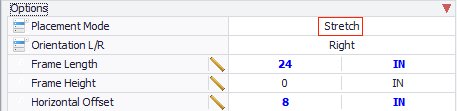
- In the Options section of the Properties dialog, select Stretch as the Placement Mode.
- (Optional)
Define the Orientation of the connecting steel frame for the support as either Right or Left.
Note: The Orientation field determines which side of the horizontal beam the connecting steel frame is placed. For example, in the bitmap below, the L-Frame had a Right orientation setting (assuming this is a Front view). This option applies to asymmetrical support frames such as L-Frames and Cantilevers which may be connected to either side of a supporting structure such as a column, wall, beam etc.
- Define the Frame length, which determines the length of the support's horizontal beam.
-
Define a Horizontal Offset for the support frame. The value here defines the distance the pipe will be offset from the original placement point of the support frame. For instance, with the L-Frame shown above, the original placement connect point is the end of the horizontal beam, so the offset will place the support frame so the pipe is offset from that point.
When placing an asymmetrical support frame such as a T or a U-Frame, the default connect point centers the pipe in the support frame, so the offset distance defined can either be applied to the right or left of center. This is done by changing the connect point in the Path Placement dialog as shown:
- Define any remaining desired properties and click OK.
- In the model, move the support frame along the pipe so it aligns with the supporting structure.
- Left-click to confirm the location.
- Use the mouse to stretch connecting steel to the supporting structure.
- Left-click to complete the procedure.